RUSTON GAS TURBINE TB5000 ENGINE DESCRIPTION
RUSTON GAS TURBINE TB5000 ENGINE DESCRIPTION
The design of the engine is fully
described in Reference 1, the following is a
brief summary.
The general layout of the engine is shown
in Figure 1. The core comprises of three
major modules: a single spool 10 stage axial
compressor, a two stage turbine and a com-
bustion system made up of six reverse flow
combustors canted and housed in a pressure
casing between the compressor and turbine
modules.
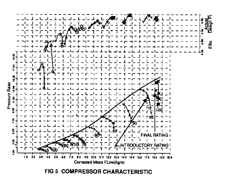
The compressor utilises 10 stages to
achieve the design pressure ratio of 14:1,
although at the current engine rating the
pressure ratio is 12.8:1. The first two stages
are transonic with a maximum tip Mach Number
of 1.1. The compressor, as shown in Figure 2,
is characterised by large chord blades which
allow aerodynamically thin sections to be used
while still maintaining adequate strength for
service durability. The first three stators
and the Inlet Guide Vane are made variable for
surge control at part speed and ultimately for
twin shaft operation.
The turbine is of two stage design,
comprising a High Pressure (HP) and Low
Pressure (LP) stages. The HP stage produces
the power required to drive the compressor,
while the LP stage produces the output power.
Both stages are of transonic design with all
the blade rows having a subsonic inlet and a
supersonic exit. The HP stage blading is
investment cast in IN939 and coated with
Sermaloy J for additional corrosion and oxidation resistance. Both blades are cooled
with air supplied internally from the com-
pressor, to reduce metal temperatures below
900° C on the stator and 800 ° C on the rotor.
The LP stage does not require cooling due to
the high temperature drop achieved across the
HP stage.
The compressor spool, which runs in two
Tilt Pad Journals, is made up of separate
discs and shafts held together via a single
central tension bolt. Location of discs and
shafts is via full ring Birth Couplings at the
outside diameter. The two turbine wheels
which are overhung relative to the compressor
spool, are also held via a central tension
stud and centralised via Birth couplings.
The drive is taken via a high speed shaft
from the end of the turbine. An epicyclic
gearbox reduces the speed from 16500 rpm to
1500 or 1800 rpm. The main lubricating pump is
mechanically driven via the gearbox. The
engine is started via a Hydro Start System,
comprising : an AC electric motor powering a
hydraulic pump and motor system, which is
engaged to the gearbox and engine via an SS
clutch.
The lubricating tank and associated system
is all housed at the cold end of the engine,
as shown in Figure 3, while the gas and liquid
fuel systems are housed immediately below the
engine for rapid response. The control system used is based on the
latest micro-processor technology and is used
on all Ruston products. It provides a fully
integrated package capable of governing,
temperature monitoring, annunciation, fault
monitoring, starting and stopping sequence
control. The power of the system also allows
options for process control, sequencing and
monitoring driven equipment. Facilities are
also provided to extend the system to cover
data logging, plant supervisory control and
financial management of complex power systems.


Comments
Post a Comment